Antenna Resonance
February 1, 2019
The majority of antenna designs are based on the resonance principle. This relies on the behaviour of moving electrons, which reflect off surfaces where the dielectric constant changes, in a fashion similar to the way light reflects when optical properties change. In these designs, the reflective surface is created by the end of a conductor, normally a thin metal wire or rod, which in the simplest case has a feed point at one end where it is connected to a transmission line. The conductor, or element, is aligned with the electrical field of the desired signal, normally meaning it is perpendicular to the line from the antenna to the source (or receiver in the case of a broadcast antenna).
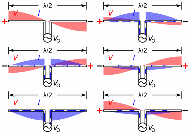
The radio signal’s electrical component induces a voltage in the conductor. This causes an electrical current to begin flowing in the direction of the signal’s instantaneous field. When the resulting current reaches the end of the conductor, it reflects, which is equivalent to a 180-degree change in phase. If the conductor is 1⁄4 of a wavelength long, current from the feed point will undergo 90 degree phase change by the time it reaches the end of the conductor, reflect through 180 degrees, and then another 90 degrees as it travels back. That means it has undergone a total 360 degree phase change, returning it to the original signal. The current in the element thus adds to the current being created from the source at that instant. This process creates a standing wave in the conductor, with the maximum current at the feed.
The ordinary half-wave dipole is probably the most widely used antenna design. This consists of two 1⁄4 wavelength elements arranged end-to-end, and lying along essentially the same axis (or collinear), each feeding one side of a two-conductor transmission wire. The physical arrangement of the two elements places them 180 degrees out of phase, which means that at any given instant one of the elements is driving current into the transmission line while the other is pulling it out. The monopole antenna is essentially one half of the half-wave dipole, a single 1⁄4 wavelength element with the other side connected to ground or an equivalent ground plane (or counterpoise). Monopoles, which are one-half the size of a dipole, are common for long-wavelength radio signals where a dipole would be impractically large. Another common design is the folded dipole which consists of two (or more) half-wave dipoles placed side-by-side and connected at their ends but only one of which is driven.
The standing wave forms with this desired pattern at the design operating frequency, fo, and antennas are normally designed to be this size. However, feeding that element with 3 f0 (whose wavelength is 1⁄3 that of fo) will also lead to a standing wave pattern. Thus, an antenna element is also resonant when its length is 3⁄4 of a wavelength. This is true for all odd multiples of 1⁄4 wavelength. This allows some flexibility of design in terms of antenna lengths and feed points. Antennas used in such a fashion are known to be harmonically operated. Resonant antennas usually use a linear conductor (or element), or pair of such elements, each of which is about a quarter of the wavelength in length (an odd multiple of quarter wavelengths will also be resonant). Antennas that are required to be small compared to the wavelength sacrifice efficiency and cannot be very directional. Since wavelengths are so small at higher frequencies (UHF, microwaves) trading off performance to obtain a smaller physical size is usually not required.

Standing waves on a half wave dipole driven at its resonant frequency. The waves are shown graphically by bars of color (red for voltage, V and blue for current, I) whose width is proportional to the amplitude of the quantity at that point on the antenna.
